
The ILS Approach Chart
- Tizi

- Apr 3
- 14 min read
Updated: Apr 3
"Oh, that's the one with the feather!"
The most famous approach in the history of instrument flying is the Instrument Landing System (ILS). The ILS is considered the only precision instrument approach available to us. As such, it is highly regarded and is very often required for use, if available, by large operator internal procedures.
For a complete guide to IFR publications, please refer to the FAA Aeronautical Chart User's Guide. This will give you life, death, and miracles of IFR charts. My article gives you the simplified cliff notes.

Basic Guidance Summary
The ILS provides angular guidance both laterally and vertically by virtue of two separate antennas:
Localizer (laterally)
Glide slope (vertically)
By angular, we mean that the precision of the guidance will increase as you get closer to the antenna station (i.e., closer to the runway).

For further details on the specific guidance and geometry, please refere to this article, here.
The Approach Plate
The approach plate - the chart - has unique elements that we will examine in this article. Be warned that this article is not all-inclusive. As new procedures are developed, you will have to use your own intellect (that's your brain) to understand what the procedure wants you to do. For the sake of this exercise, we will examine the ILS runway 10 at KSAV.
Bureaucracy and Dates and Stuff
The date the chart was last revised is reported in the bottom left corner of the plate along with its amendment version (08 November 2018, amendment 29). On the sides you will find the validity dates of the chart (valid from 19 March 2026 to 16 April 2026) - see the second image on the margins.


Top Briefing Strip

The name of the approach is reported on the top right. The name of the approach refers to the navigation equipment required for navigating the final approach segment (FAS). In our case, ILS or LOC for Runway 10. It also reports the city, airport name and identifier (SAV). Because the ILS is composed of a localizer (LOC), which is an approach type by itself, and a glide slope, this chart can be used for both LOC and ILS. For the purposes of this article, we will only focus on the ILS stuff.
On the top left of the header, the plate will report the navigation frequency. Since the ILS is a ground-based navigation approach (VLOC), you must have a frequency to tune to. In this case, the frequency is 111.35. The identifier for the localizer, needs to be verified before execution. In this case, it's I-SAV (the morse code is reported on the plan view, see later). If you have Garmin, it will identify the station for you. The channel reported below, 50, is for the Distance Measuring Equipment (DME). The (Y) just means that is a Y channel... added to increase capacity of normal DMEs. Don't worry about it.
Next to the navigation source information, you have the final approach course (FAC). In this case it's 097 degrees, which for runway 10, makes sense. This course will have to be set on your Course Deviation Indicator (CDI) and should be verified, even if the automation does it for you (in Garmin we trust). The box next to the FAC has runway information, specifically the runway landing length available (9351 ft), the Touch Down Zone Elevation (TDZE) of 30 ft, and the airport elevation of 50 ft. These numbers are very important. The runway length available is exactly how much runway you have. If there is a displaced threshold on the back end, this value will account for it, so it's very helpful for exact distances. The TDZE is useful because it can be used to change your minimums, which we'll cover later.
Middle Briefing Strip
On the left side of the middle briefing strip, we have two boxes:
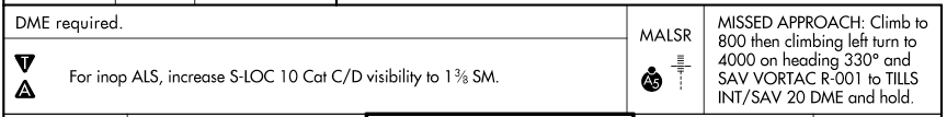
Procedure Equipment Requirements Notes Box. This includes all requirements for your navigation equipment. Since this is a VLOC approach, it will not contain any RNAV-based requirements, unless the procedure is a hybrid RNAV-ILS where you may need both. If you do, a separate box will be included, called the PBN Requirements Notes Box. In our case, the note says DME required. So we need to be able to determine distance from the localizer to execute this approach. Since we often don't have DME on a small plane, we can use GPS in lieu of DME.
Standard Procedure Notes Box. This is where we find generic notes, including alternate airport ATIS, changes to minimums with inop equipment, and more. Furthermore, there can be up to two symbols on the left side:
T - Non-standard takeoff minimums, obstacle departure procedures, diverse vector area, or close-in obstacles. If that T in the upside down triangle is there, please go read the appropriate publication!
A - Non-standard Alternate Minimums. If you planned on using this airport as an alternate for your IFR flight plan, look at the alternate minimums, cause there will be some! If there is an NA next to the A, it means that you are not authorized to use the approach for alternate airport planning.
On the right side of the strip, you have your Approach Lighting System (ALS), in our case a MALSR (pronounced Mouzer, aka "the rabbit") and your textual Missed Approach Instructions (what you do if you fail to land). The A5 next to the MALSR is the approach lighting configuration to which the MALSR belongs.
Communication Information

The bottom briefing strip, also known as your communication information, provides you with useful information in chronological order. As you approach the field, you should listen to the ATIS, then talk to approach, then to tower, and then to ground. If ATC is part-time (see the start next to appraoch and tower), you also have a UNICOM frequency. Note that the symbols in the boxes follow general conventions. The star means part-time and the L in the oval means pilot controlled lighting (PCL).
The PlanView

Ok, this one is full of stuff. Let's look at it piece by piece.
Minimum Safe Altitude
On the top left we have our Minimum Safe Altitude (MSA), which is 25 NM away from the SAV VORTAC. In order for me not to hit anything within 25 NM of SAV I need to climb to 2600 ft.

SAV Feeder Route
Here's a nerdy and important topic: beginning the approach. Back in the day, ATC services were rare, and as such, most approaches were designed to be flown without ATC vectoring you around. For you to do that, there needed to be a connection between the enroute world and the terminal world (i.e., this chart). The connection is the SAV VOR, which is found both here and on the enroute chart. If there wasn't a connection, then the chart would say 'RADAR REQUIRED' on the plan view, because there is no way for you to navigate from the enroute world to the terminal world on your own. In the case of SAV ILS 10, the SAV VOR is called a "feeder" for the approach, which means that it serves as a transition from the enroute to the terminal infrastructure. Note the thin line that goes from SAV to to TILEE. It is thin because SAV is not an initial approach fix, but it feeds you to the IAF, which is TILEE: a feeder route.

Minimum Route Altitude, Course, and Distance
Each leg of the approach will have helpful information, like your Miminim Route Altitude, your course, and distance to the next fix. In the case of the feeder from SAV to TILEE, you cannot descend below 2600 ft and you will be on R-272 for 13 NM.
NAVAIDs (VORs, LOCs, etc.)
The SAV VOR, which originates the feeder (and also defines your missed approach, as we will see later) has its own identification box with useful information, like name (SAVANNAH), identifier (SAV), frequency (115.95), morse code, and channel, 106(Y) (for the military TACAN part of the NAVAID).

The same information is provided for the localizer (LOC) antenna, which is found at the end of the runway. In our case, the box is bolded because the LOC is the primary NAVAID used for the approach.
Airports
Airport symbols depict the runways available with simple straight thin lines. Nothing special here. Note that nearby airports may be depicted if their position may be confusing to a pilot flying the approach. There's been many cases of pilots landing on the wrong field because there was another airport along the approach that was mistaken for the destination. In the case of SAV, we only have two perpendicular runways forming a cross.

Localizer Feather
The localizer feather depicts the presence of a localizer antenna. It is not to scale - it just helps the viewer recognize that LOC will be used to navigate the approach. The LOC feather will be depicted with the shaded color on the right side to show it's a front course. Some approaches use a back course (i.e., the localizer antenna is flipped backwards for convenience - like if it serves multiple runways), and the shaded colors will help you notice that (beyond the large letters 'BACK COURSE').

Fixes
Each fix on the approach has five letter identifier names, just like in the enroute world. Except we call them more commonly "intersections". On approaches, we usually call them "fixes". On VLOC approaches, these are depicted with vertical lines perpendicular to the Final Approach Course.

They are paired with a data block, which provides lots of information. In the case of TILEE, the data block shows the fix's name (TILEE) and ways of identifying it. We can use the DME from I-SAV (the localizer) of 13.7 NM. Those are called DME boats, just like the enroute world. However, if you don't have DME, then you can't identify the fix (assuming you don't have GPS). For that reason, it also says RADAR. That means that ATC can see that fix on their scope (the radar screen) and can tell you when you are at TILEE. At the very top, TILEE is also qualified as an IF/IAF which means both as an initial approach fix and as an intermediate approach fix. It's an IAF if you have to do a procedure turn outbound (the hold in lieu of a procedure turn) and it's an IF if you are inbound to the runway.
Hold in Lieu of a Procedure Turn
Because TILEE is also an IAF from the SAV feeder, one must be able to navigate inbound by themselves. You cannot turn from SAV to TILEE back to the runway... it's too sharp of a turn. Therefore, the FAA placed a hold in lieu of a procedure turn at TILEE.

The hold in lieu (from french "instead of") a procedure turn means that to turn around, you can do a hold entry procedure to turn inbound into TILEE. Once you pass TILEE the second time, it serves as your IF inbound. From SAV, this would probably be a parallel entry. This is a 1 minute hold (which applies to the entry as well) and can be flown between the block altitude 2600 to 6000 ft. If ATC needs you to, they can always say "hold as published" and you have all pertinent information displayed (inbound course 097, outbound heading 277, distance 1 minute, altitude 2600 ft). Note that the inbound course is 097 because TILEE is on the localizer. That means that if you didn't have GPS, you would be flying the hold based off of the localizer.
Approach Segments
The approach segments are in a thick black line and retain the various leg information. For example, between TILEE and SOVIE, you must be at no lower than 2000 ft on a course of 097 degrees. The distance between TILEE and SOVIE is 6 NM.

The Missed Approach
The missed approach is depicted in dashed lines. The only exception is when a procedure hold (like at TILEE) is used for BOTH a procedure turn and the missed approach. In that case, it will not be dashed.

In the case of SAV ILS 10, the missed approach is shown in dashed lines after the runway with a turn to the northwest. As a reminder, the missed approach for SAV instructs the pilot to climb to 800 ft, then left climbing turn to 4000 on heading 330 to intercept the SAV R-001 all the way to the TILLS intersection and hold. The dashed line clearly shows that left turn to intercept R-001. Because TILLS is so far off the chart, the issed approach fix and hold is shown in a separate box in the plan view. In our case, in the top right corner.
Airspaces and Geography
To provide good situation awareness, the FAA shows terrain and water (if present) as well as complicated airspace, like Special Use Airspaces. KSAV is very clearly defined by water features through the Savannah river, and has restricted airspace to the southwest. If appropriate, the FAA will also depict obstacles.

The Profile View
In my mind, the provide view is the heart of the approach, and if I had to keep one section from the entire chart (and burn the rest), this would be it. It requires analysis because the profile view is where things can get complicated between the ILS and the LOC approaches. For this article, assume we are flying the ILS. So I'll reference LOC-only stuff, but not provide too much detail. Maybe.

The profile view is shown by a thick line that leads to the runway. Some elements are repeated from the plan view, just like the hold in lieu of a procedure turn, distances, some altitudes, fix identification information, and the missed approach.
Fixes
Fixes are labeled at the top of the profile view with a dashed vertical line all the way to the ground. After all, TILEE is a lateral designation only (i.e., lat and long). The same identification information from the plan view is reported, here.

Hold in Lieu of a Procedure Turn
The hold is shown with a flat line (because you cannot descent from 2600 ft) with the block altitude 2600 to 6000 ft and a 1 minute length.

The Precision Final Approach Fix (PFAF)
As a precision approach, we need to distinguish between the non-precision FAF and the precision FAF, aka PFAF. The PFAF is defined by the lightning bolt arrow pointing at the FAF with a minimum altitude restriction. The non-precision FAF is the maltese cross (it's a templar cross, actually, but I'll shut up).

The lightning bolt arrow indicates that we can capture the vertical path (i.e., the glide slope) at or above 2,000 ft MSL. Whenever we intercept the PFAF, as long as it's above 2,000 ft, we have begun our final approach segment (FAS). To verify we are on the correct ILS beam (yeah, the ILS can have multiple false glideslopes), we should cross over SOVIE, the non-precision FAF, at the altitude reported above the maltese cross (in this case also 2000). Note that these two altitudes do not need to match. If you look at the ILS at KVDI, you will see that those two altitudes will be different.
Some instructors believe that you should stay as high as possible throughout the approach and capture the PFAF really high. In the case of the ILS at SAV, I could stay at 2600 ft until I capture the PFAF and descend. This allows you to capture the glide path earlier and stabilize earlier. Other instructors (like me) prefer to descend as low as possible as early as possible, to try and reach VMC. Again, it's a philosophy, but the chart allows you to do either.
Geometry Notes
The profile view often provides some notes concerning the geometry of the vertical path. The Threshold Crossing Height (TCH) and glide slope (GS) angle are shown if a vertical path exists. For KSAV ILS 10, the glideslope angle is 3 degrees, and the threshold crossing height for that geometry is 50 ft. These numbers are important because they affect other guidance. This approach, in fact, has another note that indicates how the Visual Glide Slope Indicator (VGSI) - which is a PAPI at KSAV - is based on a TCH of 69 ft and not 50 like the vertical glide slope! As such, they will not match. This note tells you not to be alarmed if when you go visual you see mismatching PAPIs.


Decision Altitude (DA) and LOC only Information
The profile view also includes guidance specific to LOC only approaches (ILS without GS = LOC). This article explains that stuff. The ILS minimums are based on a Decision Altitude (DA), and therefore cannot be depicted on the chart at a specific location. Instead, the thick line ends and a dashed line begins. That indicates that at some point, if you reach your DA and cannot see the runway (or ALS), you will have to execute the missed approach. Note also that this segment is called the "visual segment" because the approach will no longer protect you from anything - you are responsible from landing safely.

The LOC only data are marked with an asterisk (*) and a specific note. But be warned, the FAA is removing these asterisks. That will expect pilots to understand what is applicable to the ILS and what is applicable to a LOC. The I-SAV 3 DME point is a visual descent point (VDP) which is obviously not applicable to an ILS approach (See the LOC article instead). The I-SAV 1.7 DME is the runway, which is the missed approach point (MAP) for the LOC approach (again, not ILS, unless you circle, which gives an MDA to your circle).
Lateral Distances
Leg distances are reported - not to scale - at the bottom of the profile view. On the far right you can see the runway (thicker line).

Missed Approach
Since you will be focusing on the vertical profile as you descend to minimums, the FAA depicts the missed approach in icon format at the top right of the profile view. In the case of KSAV ILS 10, when you reach your DA, if you don't see the ALS or the runway, you have to go missed. Climb straight ahead to 800 ft, then climbing right turn to 4000 on heading 330 to intercept SAV radial 001 to TILLS and hold.

If you see the ALS, you can descend to TDZ+100 ft, which you can figure out from the header of the approach plate.
Lines of Minima
Below the profile view you will see the lines of minima. The "how low can I go" information. The minimums are categorized by equipment on the left column (ILS, LOC, circling) and by categories (A, B, C, D) on the top row. The speeds are based on final approach speed. Category A is <91 kts, Cat B is 91-121, etc.

Since we're only talking about the ILS, only the first row applies to us. The 'S' in front of ILS means "straight in". There are some approaches that are laterally angled differently and may not be considered "straight in" anymore. The minimums will reflect that angle change.
The minimums are reported in the big numbers: 230/18. That means 230 ft MSL and 1800 ft visibility (Runway Visual Range if reported). The smaller number before the parenthesis reports the minimums in AGL. So 230 ft MSL = 200 ft AGL. The values in parenthesis are military minimums that do not apply to us civilians.
The circling minimums may apply to us if we choose to do a circling approach. In that case, for category A minimums, we can fly down the ILS glide slope but stop at 520 ft. That is a Minimum Descent Altitude (MDA)! We cannot descend below that until we are in a position to land. We require 1 SM visibility (the 520-1) and we will be at 470 ft AGL. For a reminder on how to circle, see this article. As mentioned earlier, if you decide to circle, your missed approach point is now the runway.
Airport Sketch
The FAA charts also show you a summarized airport diagram to increase your situation awareness (SA). It repeats some information from the top header (so you don't have to look up and down too much), including some new stuff. The bolded 'D' at the top means 'Declared Distances', so the reported runway lengths are appropriate to be used for performance calculations. So 9,351 ft are the maximum runway length available for someone who needs to land.

The runway services by the ILS is shown in a dashed line (See runway 10). The ALS, along with slope and VGSI locations are shown (P = Papi, V = VASI). The rotating beacon is shown by the star and the control tower is labeled 'TWR'. All runway distances are provided. What is also very useful is the final approach course (FAC) on the left side (097 degrees) to help you understand how you will be approaching the runway.
Other interesting depictions could be the two arrows on runway 10/28 which like a changeover point. Those are actually arresting cables.
On the bottom, further information on the runway lights is indicated. The L in the bolded circle indicates that they are pilot-controlled during after-hour operations.


Comments